and the distribution of digital products.
Integrating Boundary Control and Safety Measures in Lane-Free Traffic Systems
:::info Authors:
(1) Mehdi Naderi;
(2) Markos Papageorgiou;
(3) Dimitrios Troullinos;
(4) Iasson Karafyllis;
(5) Ioannis Papamichail.
:::
Table of LinksThe Nonlinear Feedback Control
OD Corridors and Desired Orientations
Boundary and Safety Controllers
Appendix A: Collision Detection
Appendix B: Transformed ISO-Distance curves
Appendix D: Safety Controller Details
Appendix E: Controller Parameters
V. BOUNDARY AND SAFETY CONTROLLERSA. Lateral Boundary Controllers
\ Ensuring that a vehicle will not go beyond the road boundaries is of greater importance in a lane-free traffic environment than it is in one with lanes where vehicles tend to drive in the middle of each lane, significantly reducing the risk of going off the road. Furthermore, in dense traffic conditions of lane-free traffic, it is beneficial to have some vehicles driving exactly on a (left or right) road boundary, of course without ever violating it, because this increases the exploitation level of the available road width. Note that boundary controllers are also employed for the corridors of Section IV, whose boundaries must also be respected, even if they do not coincide with the road boundaries.
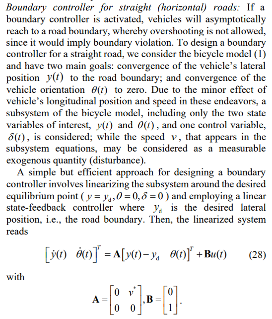
\ To this end, we deploy two boundary controllers, one for each side of the road or corridor, which provide upper and lower limits for the steering angle generated by the NLFC of the vehicle. The vehicle drives according to NLFC if such a bound is not activated; if one of the bounds is steadily activated, the vehicle is asymptotically navigated, by the action of the respective boundary controller, to the corresponding road boundary and continues driving exactly on the road boundary for as long as the steering angle produced by NLFC is activating that bound, e.g. due to sideward nudging by other vehicles. The boundary controller is first designed to handle a straight road boundary; and is eventually adapted to also accommodate circular and skewed paths.
\

\ Then, the following linear state-feedback controller can be developed for the subsystem:
\

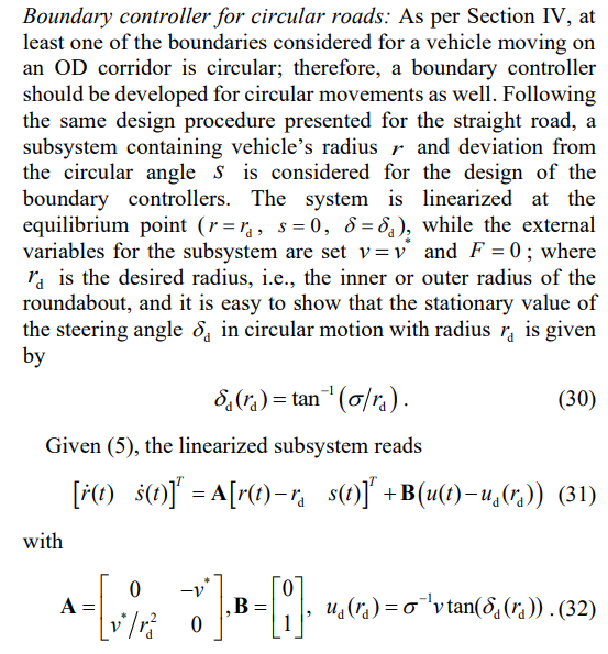
\ where K is the feedback gain, which can be readily computed to have real and negative closed-loop eigenvalues that provide asymptotic convergence of the state variables to their desired values.
\

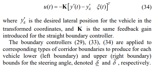
\ Then, considering (2), (31) and (32), the controller is
\

\ Boundary controller for skewed paths. For skewed boundaries, the corresponding model was presented in Section II.C, and the skewed boundary controller reads
\

\ B. Longitudinal Safety Controller
\ Since several modifications were introduced to the original NLFCs, such as different desired orientations, practical limits for the acceleration and steering angle and discrete-time implementation, the original controllers’ features, e.g. avoiding collisions, cannot be strictly guaranteed anymore. Consequently, vehicle collisions might occur in some rare severe circumstances. To prevent such situations, we develop a safety controller, imitating human drivers’ behavior, generating a safe upper limit for vehicle acceleration.
\ The general procedure pursued is summarized as follows:
\ (i) Consider the obstacles in close vicinity of the ego vehicle (EV).
\ (ii) Estimate a possible conflict position for each obstacle.
\ (iii) Select the conflict position with the shortest Euclidean distance to the EV.
\ (iv) Let a linear state-feedback controller determine a safe upper limit for the EV acceleration to ensure that no collision will occur.
\

\ Regarding (ii), a rough prediction of the short-term future path of the EV and each obstacle is performed in order to predict a possible conflict, i.e., crossing of their paths. To this end, we classify each vehicle motion into circular or skewed types, based on the value of its desired orientation. Specifically, if the desired deviation from circular angle is less than a threshold, e.g. 10, the motion is classified as circular, that means the vehicle will proceed on its current radius. Otherwise, the motion is classified as skewed, i.e., the vehicle will move along its desired orientation. After this classification, cross-points of future paths of the EV and each obstacle are determined based on the four possible notion combinations:
\ Both EV and obstacle have circular motions: There is no potential cross-point in this condition since both vehicles move in parallel.
\ Both EV and obstacle have skewed motions: In this case, a single cross-point is calculated by crossing the two vehicle motion equations:
\

\ Then, if their desired orientations are not identical (in which case their paths do not cross), the cross-point is
\

\ If the cross-point is out of the roundabout or behind the EV or the obstacle in the skewed coordinates aligned with the EV’s desired orientation, it is ignored. Otherwise, it is considered as a candidate for the closest cross-point.
\ EV and obstacle have circular and skewed motions, respectively: In this condition, computation of a possible crosspoint is slightly more elaborated and provided in Appendix D. EV and obstacle have skewed and circular motions, respectively: See Appendix D for cross-point specification.
\ In addition, the closest obstacle located in a narrow corridor around the estimated future path of the ego vehicle is identified (see Appendix D for details), and its current position is considered as a possible conflict location.
\ Regarding (iii), among all estimated cross-points and the closest obstacle position in front of the EV, the closest one is taken as the conflict point, to which the EV should maintain a safety distance by the action of the safety controller.
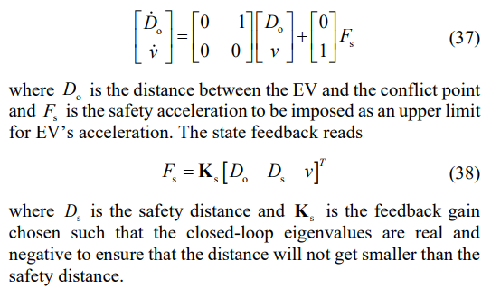
\ Finally, regarding (iv), a safety controller is designed, considering simple double-integrator dynamics to reflect the approach of the EV to the conflict point
\

\ To sum up, the structure of the overall proposed control strategy, including the nonlinear, boundary and safety controllers, is illustrated as Fig. 8.
\
:::info This paper is available on arxiv under CC 4.0 license.
:::
\
- Home
- About Us
- Write For Us / Submit Content
- Advertising And Affiliates
- Feeds And Syndication
- Contact Us
- Login
- Privacy
All Rights Reserved. Copyright , Central Coast Communications, Inc.