and the distribution of digital products.
How PAUL the Robot Tracks Its Own Movements Using Cameras and LEDs
:::info Authors:
(1) Jorge Francisco Garcia-Samartın, Centro de Automatica y Robotica (UPM-CSIC), Universidad Politecnica de Madrid — Consejo Superior de Investigaciones Cientıficas, Jose Gutierrez Abascal 2, 28006 Madrid, Spain ([email protected]);
(2) Adrian Rieker, Centro de Automatica y Robotica (UPM-CSIC), Universidad Politecnica de Madrid — Consejo Superior de Investigaciones Cientıficas, Jose Gutierrez Abascal 2, 28006 Madrid, Spain;
(3) Antonio Barrientos, Centro de Automatica y Robotica (UPM-CSIC), Universidad Politecnica de Madrid — Consejo Superior de Investigaciones Cientıficas, Jose Gutierrez Abascal 2, 28006 Madrid, Spain.
:::
Table of Links2 Related Works
3 PAUL: Design and Manufacturing
4 Data Acquisition and Open-Loop Control
4.3 Dataset Generation: Table-Based Models
5 Results
5.3 Performance of the Table-Based Models
5.5 Weight Carrying Experiments
A. Conducted Experiments and References
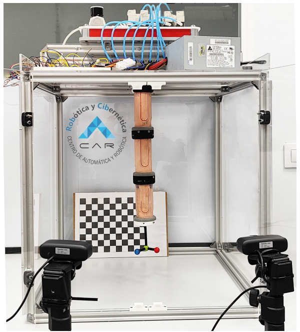
4 Data Acquisition and Open-Loop Control 4.1 Hardware SetupIn order to provide the manipulator with a solid and stable fastening system, which would also allow reliable and predictable data capture of the positions and orientations of its end, the metal structure shown in Figure 10 was built. It is a cube made of steel profiles with methacrylate sheets on the walls. The pneumatic bench, the power supply and the microcontroller were placed on top of the structure.
\ The aim of the data acquisition system is to be able to measure, whenever required, the position and orientation of the end of the robot in order to be able to relate it to the inflation times of each bladder and thus be able to create an open-loop model of PAUL. For this purpose, three elements are available: the cameras, the calibration grid and the trihedron.
\
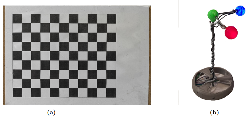
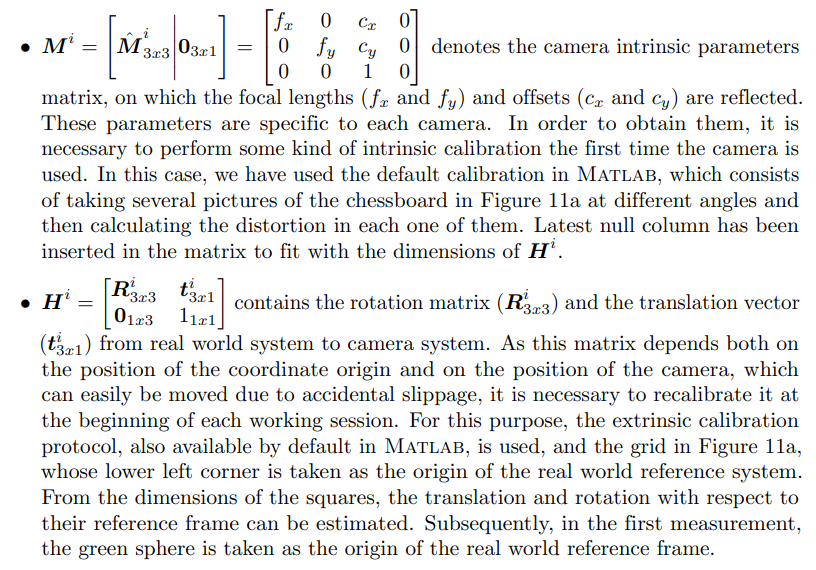
\ Two Spedal AF926H USB cameras with 1920 x 1080 px, 80◦ field of view and a frequency of 60 fps are used to capture the images. These have been placed on two tripods external to the robot’s structure. They are calibrated with a checkerboard of 11 x 8 squares of 20 mm each, which can be seen in Figure 11a.
\ The vision beacon, on the other hand, has the task of being recognised in space to determine the position and orientation of the mobile system with respect to the fixed system. The trihedron, displayed in Figure 11b, consists of three spheres, manufactured by 3D printing in PLA, inside which three LED diodes have been embedded. Thanks to these, it is possible to vary the luminosity of the spheres by means of software, keeping the system functioning correctly when the workplace or the environmental or lighting conditions vary.
\ The existence of the central rod, which moves the luminous spheres away from the base of the robot end, makes possible the spheres to be visible to the cameras in all the poses that the robot can adopt. If the spheres were otherwise directly attached to the
\
\ end of the robot, there would be numerous poses in which it would not be possible to determine the position, as the spheres would be hidden by the robot itself.
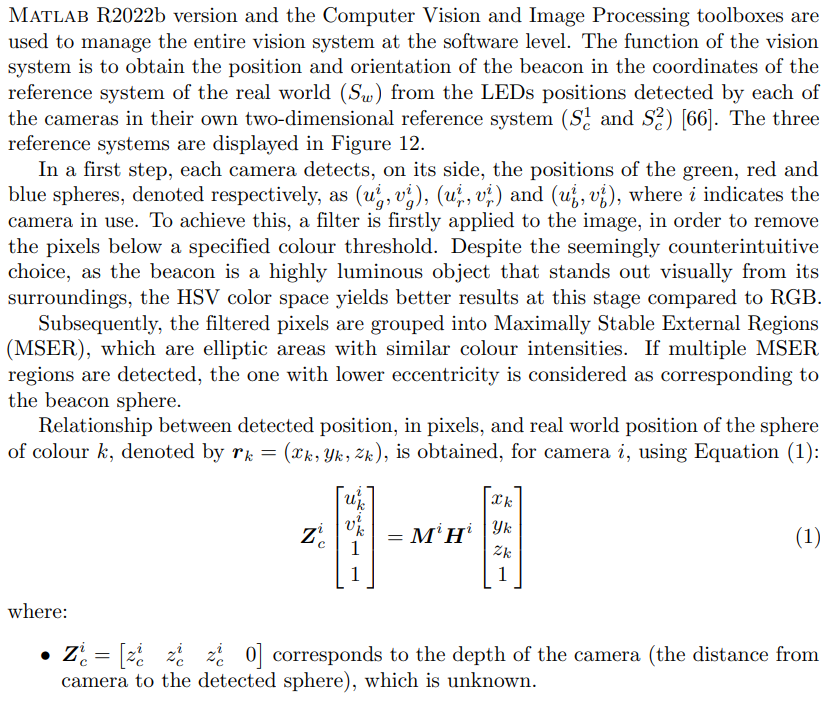
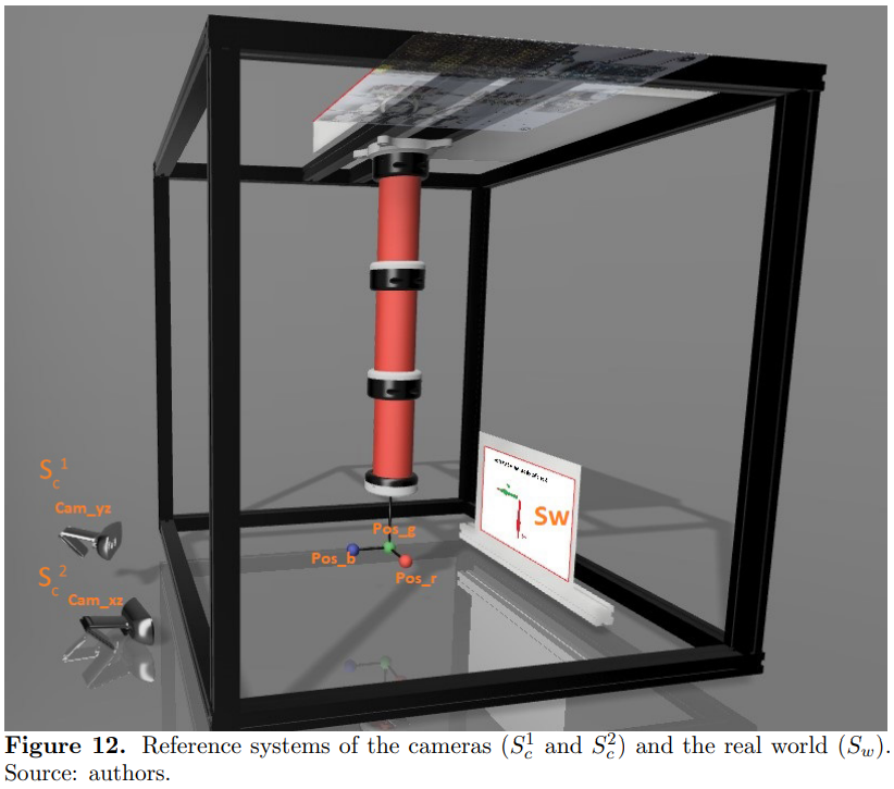
4.2 Vision Capture System\
\
\
\
\
\
\
\ \ Because coordinates of the real world are independent of the camera, if Equation (1) is applied for both cameras and rk vector cleared in the two equations, it can be said that:
\
\
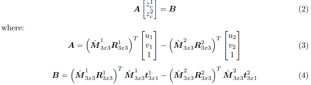
\ \ System of equations (2) can be solved using the Least Squares Method:
\
\
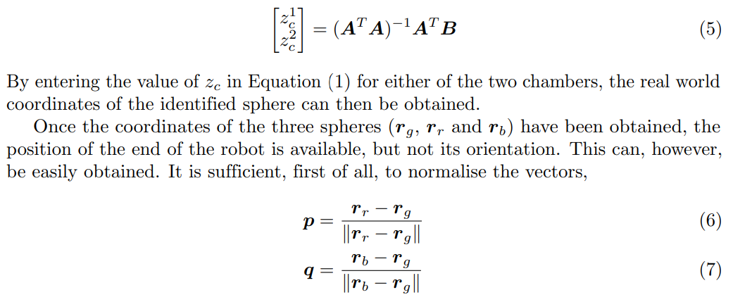
\ \ and then use the Rodrigues’ rotation formula to obtain it, respect to the real world base in the form of a rotation matrix:
\
\

\ \ and I denotes the identity matrix of size 3.
\ \
:::info This paper is available on arxiv under CC BY-NC-SA 4.0 DEED license.
:::
\